 |
|||||
 |
|||||
| About Compression Packing |
| Definition And Uses Of Compression Packing
Control of fluid loss is essential to the successful operation of mechanical equipment used in fluid handling. Various methods are utilized to control leakage at shafts, rods, or valve stems and other functional parts or equipment requiring containment of liquids or gases. The oldest and still most common of these sealing devices is compression packing, so called because of the manner in which it performs the sealing function. Made from relatively soft, pliant materials, compression or jam packings consist of a number of rings which are inserted into the annular space (stuffing box) between the rotating member, and the body of the pump or valve. By tightening a gland follower against the top ring, pressure is transmitted to the packing set, expanding the rings radially against the side of the stuffing box and rotating member, effecting a seal. 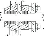 Typical stuffing box, cross section
|
Compression packing finds its major use in
the process industries such as petro-chemical, paper and steel mills, and
in the service industries like utilities, marine, water, sewage, food and
nuclear. They seal all types of fluids including water, steam, acids, caustics,
solvents, gases, oil, gasoline, and other chemicals over a broad range
of temperature and pressure conditions. They are used in centrifugal, rotary,
and reciprocating pumps, valves, expansion joints, soot blowers, and many
other types of mechanical equipment.
Compression packing is relatively easy to install and maintain. With proper attention, a high degree of successful operation can be anticipated. Successful sealing with compression packing is a function of several important related factors: 1) Careful selection of packing material to meet the specific
application requirements.
How Compression
On equipment start-up, lubricants may be released from the packing by gland pressure to provide initial lubrication and sealing. During the break-in period, these lubricants bridge the period between dry operation and the introduction of the normal lubricating system. |
Gradually, by adjustment of the gland pressure,
the pumped medium, or the external lubricating source, takes over the lubricating
function by providing a continuous source of fluid film. Gland pressure
is regulated to provide optimum lubrication to seal and prevent overheating
and consequent damage to the shaft or rod. Built-in lubricants that are
lost gradually during the operation of the equipment are compensated for
by further gland adjustment. When the volume loss of lubricated packing
approximates the original amount of built-in lubricant, the effectiveness
of the packing is lost, and replacement is required. Built-in lubricants
may also serve the important function of controlling the passage of fluids
being pumped, thus preventing excessive leakage.
Compression packing used in valved where there is slow or infrequent motion, or in static operations, is required to seal without leakage. Various impregnants may be used to assist in this function. Some packing is designed with non-migrating stable lubricants for operation under extreme pressure and temperature.
Typical stuffing box with pump suction
|
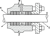 cross section A. pump suction under vacuum, leakage into pump B. fluid inlet connected to pump discharge C. atmospheric pressure D. leakage 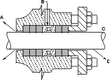 Typical stuffing box with pump pumping slurries, cross
section
Another typical stuffing box with pump
pumping slurries, cross section
|
Types of Construction
Compression packing is made in a variety of shapes, sizes and constructions, from various materials. The following is a description of basic constructions which are commonly used, and the virtues of each: Centerlock®
Centerlock® |
Plaited
Also known as braided or square plaited braid. Yarns, rovings, ribbons, and other various materials, either alone or in combination, are processed on equipment where strands pass over and under strands running in the same direction. Resulting packings are usually supplied in square cross-section, but rectangular sizes can also be braided by this method. The packing is usually soft and can carry a large percentage of lubricant. Plaited packing is easy on equipment and is generally used for centrifugal or rotary service at relatively low pressure. The packing softness makes it usable on old or worn equipment.
Plaited |
| Braid Over Core
The finished product is produced by braiding one or more jackets of yarns, rovings, ribbons, or other forms of various materials over a core, which may be extruded, twisted, wrapped or knitted. This construction allows for a wide range of densities.
Braid over Core |
Twisted
Yarns, rovings, ribbons and other forms of various material are twisted together or around a core to obtain the desired size. When metallic material is used in the packing, it can be made to resist high temperatures and pressures to resist the penetration of fluids, and to conform to the irregularities of worn equipment.
Twisted
|
Wrapped, Rolled And Folded
Strips of various material (lead, copper, aluminum, rubberized woven fabrics, etc.) are made either spirally wrapped, rolled, or folded upon themselves or around a resilient or compressible core. The rubberized fabric types are strong, dense, resilient, and are resistant to the penetration of fluids. The metallic types can also be made to resist the penetration of fluids, and can conform to the irregularities of worn equipment.
Twisted and Calendered
Plaited and Wrapped |
| How To Install Packing
Packing The Pump Correctly The importance of packing the pump correctly cannot be overemphasized. Many packing failures are due to incorrect installation
of the packing. The following steps have been devised to ensure effec-
1. REMOVE ALL THE OLD PACKING FROM THE STUFFING BOX. Clean box and shaft thoroughly and examine shaft or sleeve for wear or scoring. Replace shaft or sleeve if wear is excessive. 2. USE THE CORRECT CROSS-SECTION OF PACKING OR DIE-FORMED RINGS. To determine the correct packing size, measure the diameter of the shaft (inside the stuffing box area if possible) and then measure the diameter of the stuffing box (to give the O.D. of the ring). Subtract the I.D. measurement from the O.D. measure-ment and divide by two. The result is the required size. Cut...Don't Wind 3. WHEN USING COIL OR SPIRAL PACKING, ALWAYS CUT THE PACKING INTO SEPARATE RINGS. Never wind a coil of packing into a stuffing box. Rings can be cut with butt (square), bias or diagonal joints, depending on the con- struction. It is recommended that Centerlock® packing be cut only by butt (square) method. The following illustr- ations show these methods of preparing bulk packing. The best way to cut packing rings is to cut them on a mandrel with the same diameter as the shaft in the stuffing box area. If there is not shaft wear, rings can be cut on the shaft outside the stuffing box. |
Hold the packing tightly on the mandrel,
but do not stretch excessively. Cut the ring and insert it into the stuffing
box, making certain it fits the packing space properly. Each additional
ring can be cut in the same manner, or the first ring can be used as a
master from which the balance of the rings are cut.
Butt joint
Skive joint If the butt cut rings are cut on a flat surface, be certain that the side of the master rings, and not the O.D. or I.D. surface, is laid on the rings to be cut. This is necessary so that the end of the rings can be reproduced. When cutting diagonal joints, use a maple mitre board so that each successive ring can be cut at the correct angle. |
It is necessary that the rings be cut to
the correct size. Otherwise, service life is reduced. This is where die-cut
rings are of great advantage, as they give you the exact ring size for
the I.D. of the shaft and the O.D. of the stuffing box. There is no waste
due to incorrectly cut rings.
4. INSTALL ONE RING AT A TIME. Make sure it is clean, and has not picked up any dirt in handling. If desired, lubricate the shaft inside of the stuffing box. Seat rings firmly (except PTFE filament and Graphite yarn packing, which should be snugged up very gently, then tightened gradually after the pump is on stream). Joints of successive rings should be staggered and kept at least 90o apart. Each individual ring should be firmly seated with a tamping tool. When enough rings have been individually seated so that the nose of the gland will reach them, individual tamping should be supplemented by the gland. 5. AFTER THE LAST RING IS INSTALLED, take up bolts finger tight or slightly snugged up. Do not jam the packing into place by excessive gland loading. Start pump, and take up bolts until leakage is decreased to a tolerable minimum. Make sure gland bolts are taken up evenly. STOPPING LEAKAGE ENTIRELY AT THIS POINT WILL CAUSE THE PACKING TO BURN UP. 6. ALLOW PACKING TO LEAK FREELY WHEN STARTING UP A NEWLY PACKED PUMP. Excessive leakage during the first hour of operation will result in a better packing job over a longer period of time. Take up gradually on the gland as the packing seats, until leakage is reduced to a tolerable level. |
| Never Try To Stop Leakage Entirely, Unless
We Indicate It Is Safe To Do So
7. WHEN SPECIFIED BY THE PUMP MANUFACTURER, PROVIDE MEANS OF LUBRICATING THE SHAFT AND PACKING THROUGH THE LANTERN RING BY SUPPLYING WATER, OIL, GREASE OR LIQUID HANDLED IN THE PUMP. Fittings for this purpose are standard on many pumps.
Typical stuffing box with lantern ring,
8. IF THE STUFFING BOX HAS A LANTERN RING (SEE ILLUSTRATION ABOVE), make sure that the lantern ring, as installed, is slightly behind the fluid inlet so that it will move under the inlet as follower pressure is applied. 9. REPLACE PACKING WHEN LEAKAGE CANNOT BE CONTROLLED BY FURTHER TAKEUP ON THE FOLLOWER GLAND. 10. ON CENTRIFUGAL, ROTARY AND RECIPROCATING PUMPS, about 80% of wear is on the outer two packing rings nearest the gland. However, each additional ring does throttle some fluid pressure. On most machines, there must be enough rings so if one fails, another does the sealing, and the machine need not be shut down. |
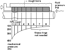 Wear /pressure load curve The mechanical pressure curve above shows eight packing rings. The first five rings do the majority of the sealing. The bottom three do little sealing, but are needed to fill the available space. The advantage of using fewer rings is less rod wear. Also, the stuffing box design is simpler and takes less material. But, wear isn't the only problem. With high temperatures, high pressures, corrosive chemicals, or abrasive particles in the fluid, more rings may be the only solution for some services. In such cases, the bottom ring contacting the fluid may have the most wear from these severe service conditions. Packing Valves Correctly
1. CAREFULLY PERFORM ALL OPERA- TIONS LISTED UNDER PUMP PACKING, STEPS 1-5. Rings used on valves and expansion joints are generally cut with a diagonal joint (illustrated below). In preparing diagonal cut (45o) rings, be sure that the first ring is cut carefully and then tested on the stem. |
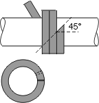
Skive joint 2. BRING THE FOLLOWER DOWN ON THE PACKING TO THE POINT
WHERE HEAVY RESISTANCE TO WRENCHING IS FELT. During this time, turn valve
stem back and forth to determine ease of turning. Do not torque down to
the point where the stem won't turn.
3. AFTER THE VALVE HAS BEEN ON THE LINE A DAY OR SO, EVEN IF NO LEAKAGE EXISTS, THE FOLLOWER SHOULD BE TIGHTENED SLIGHTLY. Obviously if leakage is occurring, the follower must be tightened. |
| Trouble-Shooting Packing Failures
Packing may fail for a variety of reasons. Beside improper installation, packing failures are often due to worn or faulty equipment, shaft misalignment, uneven take-up on the gland bolts, and other causes. If you are having trouble, carefully remove and examine the old packing set. DO NOT THROW THE SET AWAY, because it often gives clues as to the condition of the equipment, and may be the means of solving the problem. The following clues and possible causes were found by examining sets of packing which failed in service. CLUE
POSSIBLE CAUSE
|
CLUE
Excessive reduction in the thickness of the packing directly over, or in either side of the rod or shaft. POSSIBLE CAUSE
CLUE
POSSIBLE CAUSE
CLUE
POSSIBLE CAUSE
CLUE
POSSIBLE CAUSE
CLUE
POSSIBLE CAUSE
|
CLUE
Rings next to gland follower badly damaged, with bottom rings in fair condition. POSSIBLE CAUSE
CLUE
POSSIBLE CAUSE
CLUE
POSSIBLE CAUSE
Grateful acknowledgement to the Fluid Sealing Association in their role in the compilation of About Compression Packing. |
| Phelps Industrial Products, Inc., 6300 Washington Boulevard, Elkridge, Maryland 21075-5397 |